Wednesday, 23 December 2015
Tuesday, 10 November 2015
Branch Joints - part 1
Branching joints is a topic I've been interested in for a while. In researching this area I've read a variety of techniques, each having interesting ideas in their own right but not altogether robust solutions for my needs.
Recently I came across a great article which presents a pro/cons and comparison of the various techniques, then presents a different and more robust branch joint solution. Basically the key realisation is that the problem can be boiled down to 2 main areas convex hull construction and subdivision loop method.
Procedural Tree Generation: Modelling Branching Structures as Subdivision Surfaces
The following proof of concept demonstrates a trivial case for performing branching joints
In order to test the join process, firstly copying Tubes of various size and resolution to Tetrahedron points resulting in the above geometry
The tubes are Mesh geometry not polygons, this allows to carve off the end edge loops
Number simply illustrate that each has different point counts
Tetrahedralize SOP is used to generate a convex hull geometry
The convex hull creates geometry superfluous to need, which can be rectified by taking the dot product of the primitive normals of the convex hull source geometry and convex hull itself
Geometry can be removed where it satisfies certain criteria produced by the dot product
Merging tubes with convex hull, perform cleaning with PolyDoctor SOP correct winding of polygons and creating vertex normals
Finally a Subdivision SOP using the method of OpenSubDiv Loop generates the best results, others cause rippling effects
Tuesday, 13 October 2015
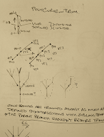
Polygon Curve Carving
After finding that the Carve SOP doesn't allow the use of attributes, thought I'd give making my own version that handles custom attributes and parameter expressions. Currently for my purposes I only need to carve polygon curves, so it shouldn't be too difficult. Later I might tackle other curve types, nurbs, bezier. If all goes well and I have the time, I would like to try surface carving but it might out of reach.
To define the polygon curve carve tool for development, I started by analysing the workings of Houdini's native Carve SOP. Firstly, there's quite a significant difference in the way it handles polygons v nurbs curves. In short the poly curve carving implementation is basically a case of removing and positioning points, where as with nurbs it's quite a different story, involving a number of high order concepts, eg. Knot insertion, corner cutting, interpolation etc.
I generally begin by nutting out the implementation detail, when developing any tool. This process helps break down a problem into manageable pieces and involves lots of sketching, working through scenarios to build an idea of how the carve tool in this case should operate.
Version
|
1.0.0
|
Build
|
14.0.361
|
Friday, 9 October 2015
Python hou.runVex()
In a previous post I managed to find and implement the math required to find intersection point between 2 lines in 3D, which was interesting and a challenge.But in that and other situation I often wonder how I can exploit Houdini more when it comes to this kind of math, as Houdini's nodes already implement so much. Quite commonly cases arise where I'd like to run some python code against a node, ie. Invoke a node, pass some geometry and return the output.
That's where I got to thinking that VEX actually has a lot of powerful functions that Houdini's python doesn't, Then I remembered coming across the hou.runVex() method. After spending the best part of a week getting to grips with this workflow, thought I'd write down some of my findings, since there's not much out there on this topic.
Things of note when using hou.runVex(vexfile, inputs)
- The inputs argument can't be an empty dictionary, even if there aren't arguments defined on the cvex function.
- I've found that cvex must be the context function, at least when working with the Python SOP. Although don't quote me on that needs more testing.
- When compiling, it's safest to rename the .vfl when changes are made, at least for a successful compilation to vex. e.g.. Say you have a file named attrib.vfl and you compile it to attrib.vex successfully, upon making code changes to the .vfl it's safer to rename the file attrib_01.vfl and compile this to a corresponding .vex file. This will ensure that the vex file reflects the changes.
- There's conditions to passing lists or arrays in the inputs dictionary, they must have the same length and each lists items must be of the same type.
- Also related to input arguments having length > 1 , e.g. Lists or arrays. Theses types will affect the exports/bound variables length, causing outputs to also display matching length even when their default value is of a single value.
- Another point worth noting regarding inputs when using lists is that they effectively form a kind of loop, running the vex code as many times as there are items in the list. This ability could be utilised to emulate functionality akin to the vex/vop nodes parameter run over : points, prims, vertices, detail.
- It also seems, a least for vector type inputs, they must be contained in a list or array type, ie When passing a single vector, it will need to be in an list of 1 item, or the function's input argument default defined in vex will be used. This doesn't seem to be the case with strings or integers, which makes me wonder whether it's due to vector types having native length in it's components.
- This point needs more testing, getting some very strange results which are difficult to track down.I think there is a memory issue, although it could be due to way vex works! Not entirely sure. Can't recall exactly, but in the docs it talks about how vex is compiled and that it doesn't allow for recursive code. One odd effect of running vex via Python in this way, is that you can refer to the returned value before you've made the call. eg
I think there maybe a memory related issue, because although the vex is running as expected, it seems to store the result in memory and that's why the above call to variable "a" before it's definition works, occasionally. Now when I change position values via an upstream transform node, the results of the vex also transform when they definitely shouldn't be. The kicker is when I save the hip with the upstream xform and reopen the hip the results are as expected. Also the variable ref that was working now doesn't, errors as expected. which brings me back to the vex in memory being the problem.print a a = hou.runVex() This will work fine! Then again it doesn't, as it shouldn't.
In Short, It works! Mostly.
As long as the above points are considered, hou.runVex() should work as expected. This workflow has the potential to be very helpful and powerful, which I'd like to use more often. Though the last point is a bit of a concern.
As long as the above points are considered, hou.runVex() should work as expected. This workflow has the potential to be very helpful and powerful, which I'd like to use more often. Though the last point is a bit of a concern.
Wednesday, 7 October 2015
Intersection Point of 2 lines in 3D
After spending some time researching ray tracing implementation and solving simultaneous equations, I had the feeling there should be vector formulation to this problem. Anyway since I'm not a mathematician I wasn't going to easily happen upon the answer by myself. As it happens The vector form of the solution did exist and I was able to find it at the following links.
The Math Forum : Vector Algebra - Finding the Intersection Point
Math Stack Exchange : Find intersection of two 3D lines
As this work is related to a broader set of tools I'm developing, the code is implemented in python. Although the same could be done in VEX or VOPS.
The Math Forum : Vector Algebra - Finding the Intersection Point
Math Stack Exchange : Find intersection of two 3D lines
As this work is related to a broader set of tools I'm developing, the code is implemented in python. Although the same could be done in VEX or VOPS.
Saturday, 12 September 2015
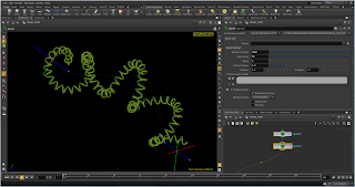
Spiral Along Curve
The Spiral tool is a SOP node mainly implemented in the VOP context. Working in 2 distinct modes, firstly as a Spiral geometry generator, similar in functionality to the Line SOP as it effectively extends the Line SOP. Secondly and more interestingly the Spiral SOP is build upon input geometry, eg. If the input is a line or curve the spiral will be defined by that geometry and the spiral can orient along that line/curve.
In the below screenshots I've setup 2 nulls which define the start and end points to a 4th order nurbs curve, to demonstrate the ability of the Spiral SOP.
By changing the start and end points positions, the spiral seamlessly windes around the underlying curve. Another handy and powerful use is chaining, more complex spirals can be created by this method, this can be seen in the last screenshot were I've created a coiled cable similar to an old phone cable.
DOWNLOAD
DIGITAL ASSET
HIP
Build 14.0.361
Version 2.0.0
Sunday, 28 June 2015
Diffusion Limited Aggregation over 3D Surfaces
Here is a preview of the results from a DLA system created primarily with the Solver SOP.
What you can see is every tenth frame of the systems growth, what you don't see is the systems simulation frames. I created a method to only save .pc files as the current point became part of the growth system, omitting the points during their random walk towards the growth system.
Also it's not immediately obvious but the point in the growth system are actually moving over the convex surface.
There are a bunch of useful point and detail attributes created for the system, eg. creation frame, life etc.
Also here is a clip showing the simulation process, to get a nice formation it can take a long time. I do envisage that once some efficiencies are made and the system is turned into an asset, it could be tweaked to run faster. Although I guess, that's also the nature of sims.
If you'd like to find out more about the math and logic involved, my system is loosely based on the of Robert Walker.
Monday, 15 June 2015
DOP Multiple Cloth Objects using Copy SOP
Multiple Cloth Objects can be created using the Cloth Object DOP, where the Initial Geometry contains multiple pieces of geometry, e.g.. Grids. (In many cases this geometry would be created by way of the Copy SOP). Actually to be more specific the key is Primitive Groups not so much pieces of Geometry, although those usually coincide.
Before continuing, I have to mention that although this process technically does as it says. The aim was to constrain each Cloth Object individually and dynamically(number of Cloth Objects). I have found it didn't give me the outcome I was looking for, ie. Constraints only work on a single Cloth Object, however I do think the may be a way, possibly using Copy Data DOP.
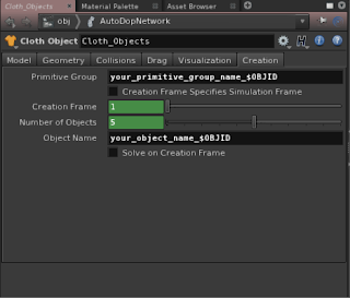
On the Creation tab of the Cloth Object DOP changing the following parameters:-
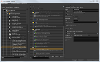
Now this setup so far will create x number Cloth Objects with exactly same Geometry! So the trick is to isolate the Geometry for each Cloth Object based on the Primitive Groups created in the SOP context, in this case by way of the Copy SOP. As you'll notice there isn't any Group or Primitive Group parameters on the Cloth Object. You can however add the appropriate parameter, by editing the parameter interface of the Cloth Object DOP you can add a parameter - Primitive Group. It can be found via the Create Parameters - From Nodes tab, expand +Cloth Object + clothconfigureobject1 + sopgeo_initialgeometry1(Geometry) + Primitive Group (primgroup). move the parameter to the Cloth Object Creation tab. Finally in the Primitive Group parameter place an appropriate group name followed by the object id variable : "your_primitive_group_name"`$OBJID` note : $OBJID could be affected by other simulation objects

Before continuing, I have to mention that although this process technically does as it says. The aim was to constrain each Cloth Object individually and dynamically(number of Cloth Objects). I have found it didn't give me the outcome I was looking for, ie. Constraints only work on a single Cloth Object, however I do think the may be a way, possibly using Copy Data DOP.
On the Creation tab of the Cloth Object DOP changing the following parameters:-
- Number of Objects : This would contain an expression that equates to the number of copies required, this will depend on your particular setup.
- Pointing to the Number of Copies parameter of the Copy SOP using ch("your_copy_sop_location/ncy") would be one way.
- Using the npoints("your_copy_sop_location") expression could also be used when there are Copy SOP Template Points being used
- Object Name : "name_prefix" $OBJID note : Quotes aren't required for the name_prefix
Now this setup so far will create x number Cloth Objects with exactly same Geometry! So the trick is to isolate the Geometry for each Cloth Object based on the Primitive Groups created in the SOP context, in this case by way of the Copy SOP. As you'll notice there isn't any Group or Primitive Group parameters on the Cloth Object. You can however add the appropriate parameter, by editing the parameter interface of the Cloth Object DOP you can add a parameter - Primitive Group. It can be found via the Create Parameters - From Nodes tab, expand +Cloth Object + clothconfigureobject1 + sopgeo_initialgeometry1(Geometry) + Primitive Group (primgroup). move the parameter to the Cloth Object Creation tab. Finally in the Primitive Group parameter place an appropriate group name followed by the object id variable : "your_primitive_group_name"`$OBJID` note : $OBJID could be affected by other simulation objects
The following screenshots show the Cloth Object and Geometry Data before and after the changes. Notice the standard setup Cloth Object contains all the copied geometry points, apposed to the altered setup, has multiple objects which only contain a subset of geometry based on the primitive group/s.

Labels:
Cloth,
Constraints,
Copy,
DOP,
Houdini,
Primitive Groups
Monday, 9 February 2015
Matrix Rotation
Here are 2 examples of using a matrix to perform rotation of an object about a pivot point, implemented in the VOP SOP context and VEX code in both the point and attribute wrangle nodes.
Labels:
Attribute Wrangle,
Matrix,
Point Wrangle,
Rotate,
VEX,
VOPS
Monday, 19 January 2015
Get Primitive's Points with VEX
Note:
Code below was developed for Houdini 13
Since Houdini 14 the primpoints(int input, int @primnum); function returns an array of points per primitive. Obviously a much better solution
Attribute Wrangle in Detail Attribute mode
The following VEX code returns the points associated with the given primitive. In this case the primitive is chosen based on the proximity to the current point, using the xyzdist() function, where the first argument is the geometry containing the primitives to test against the current point, argument defined as "1" gives access to the second input of the attribute wrangle node.
i@prim;
v@uv;
float dist = xyzdist(1, @P, @prim, @uv);
//Above gets the prim(n) and prim(uv) for a given point position
//Also the distance between the given point and the prim returned
//Although all we really need is the primitive number
//--
//Create array to store the primitive's point numbers
int primpoints[];
v@primpoints;//This vector is used to store the 3 points instead of using an array, due to a limit with array attributes.
NOTE:
Basically if you want to access the array in another wrangle further down the chain, you need to use a data type other than an array instead, a vector or matrix can be used to store array like data structures.
//Get the number of vertex for a given prim
int nvtx = primvertexcount(1, @prim);
//Loop over the vertercies to find their associated points
for (int i = 0; i < nvtx; i++){
//Get the linear vertex numbers for the prim(n)
int linearvertex = vertexindex(1, @prim, i);
//Get the point number from the linear vertex number
int vertexpoint = vertexpoint(1, linearvertex);
//Put point numbers into the points array
primpoints[i] = vertexpoint;
@primpoints[i] = vertexpoint;
}
//Display primitive's point numbers
//printf("%g \n", points);
Code below was developed for Houdini 13
Since Houdini 14 the primpoints(int input, int @primnum); function returns an array of points per primitive. Obviously a much better solution
The following VEX code returns the points associated with the given primitive. In this case the primitive is chosen based on the proximity to the current point, using the xyzdist() function, where the first argument is the geometry containing the primitives to test against the current point, argument defined as "1" gives access to the second input of the attribute wrangle node.
i@prim;
v@uv;
float dist = xyzdist(1, @P, @prim, @uv);
//Above gets the prim(n) and prim(uv) for a given point position
//Also the distance between the given point and the prim returned
//Although all we really need is the primitive number
//--
//Create array to store the primitive's point numbers
int primpoints[];
v@primpoints;//This vector is used to store the 3 points instead of using an array, due to a limit with array attributes.
NOTE:
Basically if you want to access the array in another wrangle further down the chain, you need to use a data type other than an array instead, a vector or matrix can be used to store array like data structures.
//Get the number of vertex for a given prim
int nvtx = primvertexcount(1, @prim);
//Loop over the vertercies to find their associated points
for (int i = 0; i < nvtx; i++){
//Get the linear vertex numbers for the prim(n)
int linearvertex = vertexindex(1, @prim, i);
//Get the point number from the linear vertex number
int vertexpoint = vertexpoint(1, linearvertex);
//Put point numbers into the points array
primpoints[i] = vertexpoint;
@primpoints[i] = vertexpoint;
}
//Display primitive's point numbers
//printf("%g \n", points);
Subscribe to:
Comments (Atom)


